what type of fill is best to spread in a home crawl space?
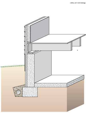
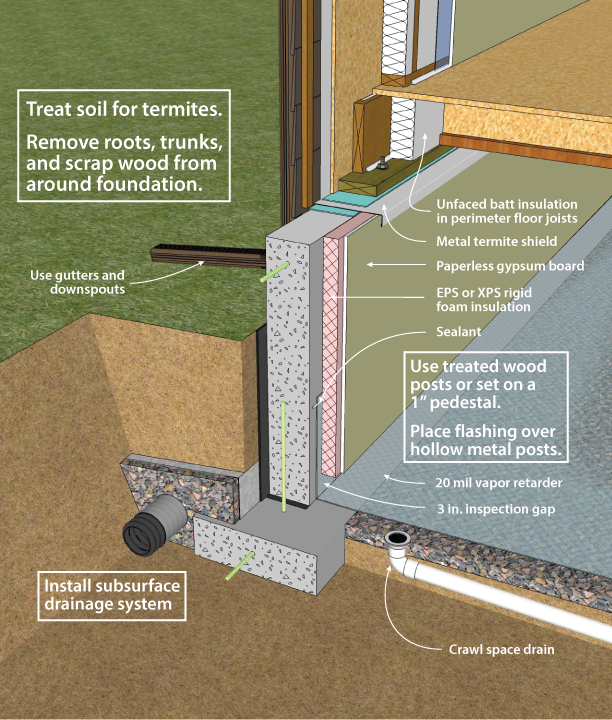
Effigy 3-ane. Concrete Crawl Infinite Wall with Exterior Insulation
iii.one Recommended Pattern and Construction Details
VENTED VERSUS UNVENTED Crawl SPACES
The principal perceived advantage of a vented crawl infinite over an unvented i is that venting may limit radon and moisture-related decay hazards past diluting the clamber space air. Additionally, providing a vented crawl infinite may make sense in overflowing-prone areas such equally coastal zones subject area to hurricanes. Venting can complement other wet and radon control measures such equally basis embrace and proper drainage. However, although increased air flow in the crawl infinite may offering some dilution potential for ground source moisture and radon, information technology will not necessarily solve a serious trouble. Vented crawl spaces are frequently provided with operable vents that tin be closed to reduce winter rut losses, just as well potentially increment radon infiltration. Although not their original purpose, the vents tin also exist airtight in summer to continue out moist exterior air that tin accept a dew point above the crawl infinite temperature. This arroyo, withal, requires a high level of informed occupant participation to exist successful.
Unvented (conditioned) crawl spaces are generally preferred in most cases, except where inundation risks are exceptionally high, as in littoral zones subject to hurricane flooding. The principal disadvantages of a vented clamber space over an unvented one are that (1) pipes and ducts must be sealed and insulated against heat loss (cooling loss in the summer) and freezing, (ii) a larger surface area (the clamber space ceiling typically is larger than the area of the clamber space walls) commonly must be insulated, which may increase the cost, (three) under hot humid conditions warm humid air circulated into the cool clamber space can cause excessive moisture levels in structural wood components (especially floor joists) that can cause mold and decay, and (4) an airtight, continuous thermal envelope at the clamber space ceiling is very difficult to achieve in practise. It is not necessary to vent a crawl space for moisture control if it is open to an adjacent basement, and venting is clearly incompatible with crawl spaces used as conditioned air distribution plenums. In fact, at that place are several advantages to designing clamber spaces as semi-conditioned zones. Duct and pipe insulation tin be reduced, and the foundation is insulated at the crawl space perimeter instead of its ceiling. This commonly requires less insulation, simplifies installation difficulties in some cases, and tin be detailed to minimize condensation hazards.
Although unvented clamber spaces take been recommended, "except under severe moisture conditions," past the University of Illinois'south Small Homes Council (Jones 1980), moisture issues in crawl spaces are mutual enough that many agencies are unwilling to endorse closing the vents year-round. Soil type and the groundwater level are cardinal factors influencing moisture atmospheric condition. It should be recognized that a crawl space can be designed as a brusque basement (with slurry slab floor), and, having a college floor level, is subject to less wet run a risk than a basement in most cases. Viewed in this way, the main stardom betwixt unvented crawl spaces and basements is in the owner's accessibility and likelihood of noticing wet problems.
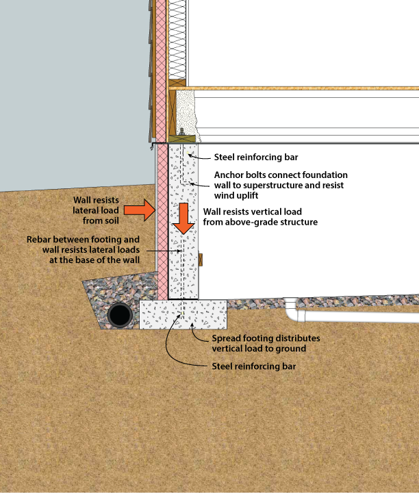
Effigy 3-ii. Structural System Components of a Crawl Space
STRUCTURAL DESIGN
The major structural components of a crawl infinite are the wall and the footing (see Figure 3-ii). Crawl space walls are typically constructed of cast-in-place concrete, concrete masonry units, or alternative systems like insulated concrete forms (ICFs). Clamber space walls must resist whatever lateral loads from the soil and vertical loads from the structure above. The lateral loads on the wall depend on the meridian of the fill, the soil type and moisture content, and whether the building is located in an area of low or loftier seismic activity. Because of the large number of variables involved in foundation structural blueprint, last determination of wall thickness, concrete force, footing dimensions, and reinforcing should be made after consultation of locally-enforced building codes or design by a licensed structural engineer.
In place of a structural foundation wall and continuous spread footing, the structure can exist supported on piers or piles with beams in between. These beams between piers support the structure in a higher place and transfer the load dorsum to the piers.
Physical spread footings provide back up beneath physical and masonry clamber infinite walls and/or columns. Footings must be designed with adequate size to distribute the load to the soil. Freezing h2o below footings can heave, causing bang-up and other structural problems. For this reason, footings must be placed beneath the maximum frost penetration depth unless founded on bedrock or proven non-frost susceptible soil or insulated to prevent frost penetration. Since the interior temperature of a vented crawl infinite may be below freezing in cold climates, footings must be beneath the frost depth with respect to both interior and exterior grade unless otherwise protected.
Where expansive soils are nowadays or in areas of loftier seismic activity, special foundation structure techniques may be necessary. In these cases, consultation with local building officials and a structural engineer is recommended.
WATER / MOISTURE MANAGEMENT
While the crawl space is not meant to be living space (such as a basement), it is still very of import to command the amount of wet that tin build up in that space. High levels of humidity at relatively low temperatures can cause condensation on unlike surfaces within the crawl infinite. This condensation can crusade wooden support structures to rot, decreasing their structural integrity. Condensation and loftier levels of moisture besides create an environment that is conducive to mold growth, which tin have adverse effects on the health of the dwelling's inhabitants.
In general, wet management schemes must command h2o in 2 states. Get-go, since the soil in contact with the foundation wall is ever at 100% relative humidity, foundation walls must deal with h2o vapor that volition tend to migrate toward the interior nether most conditions. 2d, liquid h2o entry must be prevented. Liquid water tin can enter from sources such as:
- Uncontrolled flows of surface water
- High water table
- Capillary period through subsurface foundation assemblies
There are two principal configurations for crawl spaces: vented and unvented. The vented crawl infinite has historically been the near widely employed design. It works by allowing exterior air to menstruation through the crawl space, thereby, in theory, removing the backlog moisture and assuasive information technology to dry (Davis et al. 2005). Unvented clamber spaces (also known as closed or conditioned) exercise not accept vents to the exterior and rely on limiting moisture intrusion from the soil, forth with mechanical drying mechanisms such equally air conditioning or a dehumidifier to forbid moisture build-upward (Dastur et al. 2005). For both vented and unvented designs, at that place are mutual techniques that are used to limit the moisture content in the crawl infinite. These techniques include methods for blocking moisture sources by providing proper drainage, vapor retarders and air barriers. Additional methods for removing moisture build upwards in the clamber space are as well employed.

Effigy 3-3. Crawl Infinite Drainage: Clamber Space Flooring At or Above Grade
The post-obit construction practices will prevent excess water in the form of liquid and vapor from infiltrating the crawl space. These techniques are shown in Figures 3-3, 3-4, and three-five.
- Manage outside ground and rain h2o by using gutters and downspouts and by grading the basis around the perimeter at least six inches of autumn over ten feet of run. Install a foundation drain (if applicable) and apply water-proofing to the foundation walls. If crawl infinite admission is from the outside, locate the admission door at to the lowest degree four inches above the footing (Dastur et al. 2005).
- Add dorsum fill material or a drainage mat around the foundation that is gratuitous draining to allow basis or rain water to bleed down to the perimeter drain if one is installed at the base of operations of the footing. At that place are a diverseness of approaches to ground drain design that are discussed in the adjacent department.
- Add a capillary break (a airtight cell foam sill sealer or gasket) between the acme of the concrete and the sill plate to forbid moisture migration from the concrete foundation to the floor structure above. In unvented crawl spaces, install a capillary suspension between the basis and the concrete wall (BSC 2006) to limit the amount of ground water absorbed through the ground. If the floor of the crawl space is above the meridian of the footing, soil volition be in contact with the interior side of the foundation wall above this capillary break, allowing moisture to be introduced into the wall via capillary suction. Install waterproofing to eliminate this capillary connectedness (see Figure iii-3).
- Prevent evaporation from the ground to the interior past covering the entire ground with a poly vapor retarder, lapping seams at least vi inches and sealing them with duct mastic. The ground vapor retarder textile should be extended up onto the wall. The vapor retarder material should be structurally attached to the wall using a batten strip termination at the top border, and sealed. For vented crawl spaces, the unabridged wall should exist covered, leaving just a three inch termite inspection gap between the summit of the wall and the sill plate (Marshall 2008). For insulated foundations, a lower termination is viable. For cases where the vapor retarder will be the final finished floor surface, a 20-mil, fiber reinforced material is recommended. Such a vapor retarder makes for an effective clamber space liner because it is durable and tear/puncture resistant, making it possible to walk or clamber on it while keeping moisture in the ground from diffusing into the crawl infinite (Marshall 2008).
- Where applicable, include a four-inch deep, 3/four-inch diameter (no fines) stone bed above the footing and right below the vapor retarder. This functions equally a granular capillary intermission beneath the vapor retarder, a drainage pad, and a sub-crawl space liner air pressure field extender for the soil gas ventilation organisation.
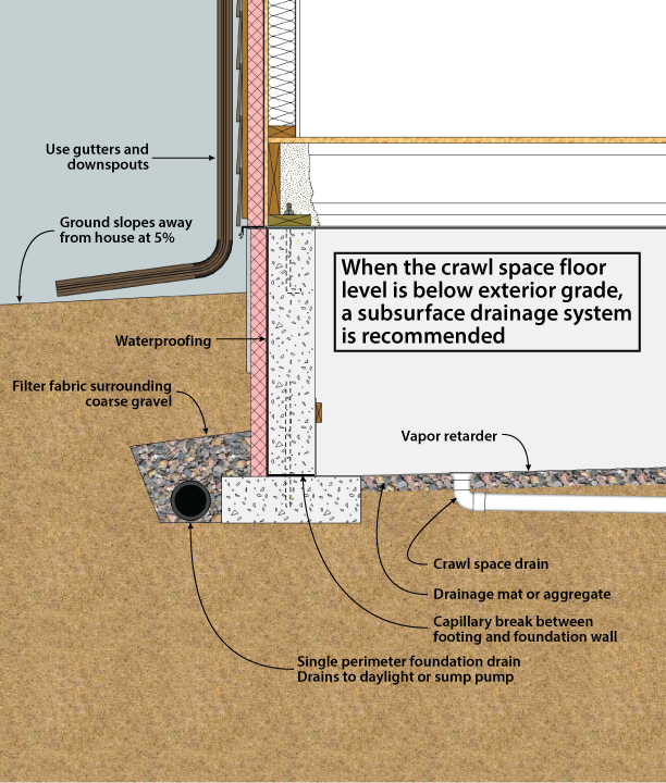
Figure three-4. Crawl Infinite Drainage: Clamber Space Below Grade
Even afterward employing an effective crawl infinite drainage and vapor retarder organization, it is yet possible for moisture to find its fashion into the crawl infinite. In a vented crawl space, cooler temperatures may crusade wet in humid air to condense on the walls, ceiling, and on the ground. Some other possible source of moisture accumulation inside the crawl space is pipe leaks. These sources can create pools of water that need to be evacuated. This tin can be achieved past grading the crawl space floor and by installing a drain or sump pump at the low point. (Dastur et al. 2005). It is important to complete the internal drainage system early on in the construction to forbid moisture buildup that can occur before the roof is completed.
Concrete foundation walls comprise water from when they were poured which needs to be prodigal past allowing them to dry. In cases where the majority of the wall is below grade, it can simply dry to the interior. The insulation material and the wall covers placed on the walls during the construction of the crawl space deed as vapor retarders, not allowing the walls to dry to the interior. For this reason, it is recommended that these wall coverings be installed near the cease of construction to allow for every bit much drying of the concrete as possible (BSC 2006).
In unvented crawl spaces it is important not only to have an effective vapor retarder, but too to accept a complete air barrier. For this reason, all gaps between the foundation wall and sill plate, sill plate and ring joist, and ring joist and subfloor should be sealed. All gaps and penetrations in the foundation wall also need to be adequately sealed. A tight air barrier will prevent the influx of humid outside air through air send, creating an interior space that is contained of exterior wet weather condition. To further split up the conditions in the crawl space from those of the outside, mechanical drying systems such as a stand-alone dehumidifier should be used (Dastur et al. 2005). Alternately, the ductwork system can include the clamber infinite in the supply / return cycle to effectively treat it every bit an interior infinite.
To further split the conditions in the crawl space from those of the outside, mechanical drying systems such as a stand-alone dehumidifier should exist used (Dastur et al. 2005).
- All water belch from appliances should exist terminated to the outside or to a sealed sump.
- All kitchen and bath exhaust vents should terminate to the outside.
- If fuel-fired appliances are used and located in an unvented clamber infinite, ensure that their air intake and exhaust are both routed straight to the outside.
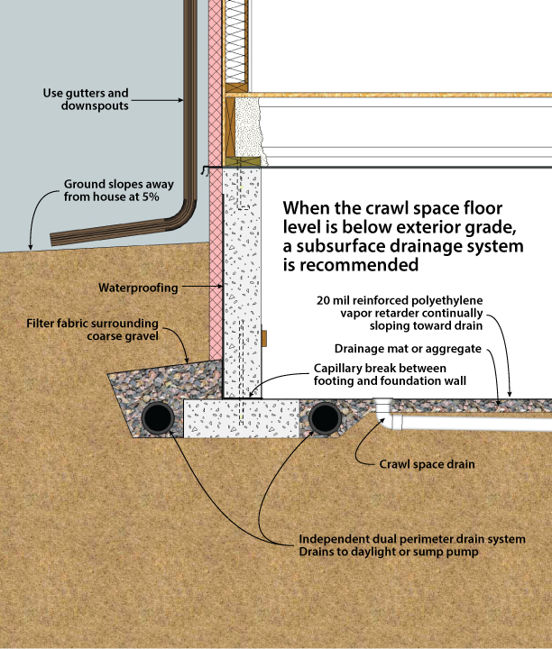
Figure three-v. Crawl Infinite Drainage: Clamber Space Below Course with Dual Drains
DRAINAGE AND WATERPROOFING
Although a crawl space foundation is not intended as living space, information technology is highly desirable to continue it dry. Good surface drainage is always recommended and, in many cases, subsurface drainage systems may be desirable. The goal of surface drainage is to keep h2o away from the foundation by sloping the ground surface and using gutters and downspouts for roof drainage.
Figure 3-3, 3-4, and 3-5 describe 3 different drainage techniques for crawl spaces. Figure 3-3 applies when the crawl infinite floor is flush with (or to a higher place) the surrounding grade. In most cases, this type of crawl infinite volition not require perimeter drainage. On especially wet sites, or on sloping sites where role of the crawl infinite floor is beneath-grade, it may all the same be wise to install a perimeter drain system, described below. If the crawl space flooring is higher up the superlative of the ground as shown, apply waterproofing on the interior confront of the buried foundation wall to avoid capillary suction of water into the concrete.
Figure three-4 and 3-5 describe foundation drain systems, which are recommended for all clamber spaces where the floor is below the level of the surrounding grade. On especially dry sites, it may be possible to eliminate the drainage organization and not experience moisture problems. In most cases, a subsurface perimeter drainage system similar to that used for a basement is recommended (see Figures three-4 and three-5). Figure 3-5 describes the recommended best do. It consists of ii independent loops of perforated foundation drain, one inside the basis and i exterior. These drain independently, either to daylight or to an internal sump. Effigy 3-4 shows some other choice that is appropriate when site drainage conditions are good. There is no provision for drainage of the space inside the footings. Its single loop of foundation drain is on the outside of the footing, and drains to daylight or to an internal sump. It should exist noted that the duct connection to the exterior of the ground can reduce the effectiveness of subslab depressurization radon mitigation systems by reducing the ability of the system to maintain sufficiently low pressures beneath the slab.
The final line of defence force— waterproofing—is intended to go on out water that finds its manner to the wall of the structure. First, information technology is important to distinguish between the need for dampproofing versus waterproofing. In most cases a dampproof coating covered by a 4-mil layer of polyethylene is recommended to reduce vapor and capillary draw transmission from the soil through the basement wall. A dampproof coating, however, is not effective in preventing water under hydrostatic force per unit area from entering through the wall. Waterproofing is recommended (one) on sites with predictable h2o problems or poor drainage, (2) when the clamber space is intended for use equally storage or houses mechanical equipment or (three) on any foundation built where intermittent hydrostatic pressure occurs confronting the basement wall due to rainfall, irrigation, or snow melt. Except on very dry out sites, it is generally recommended to use waterproofing as a best practice. On sites where the clamber space floor could be beneath the water table, a slab-on-grade foundation is recommended.
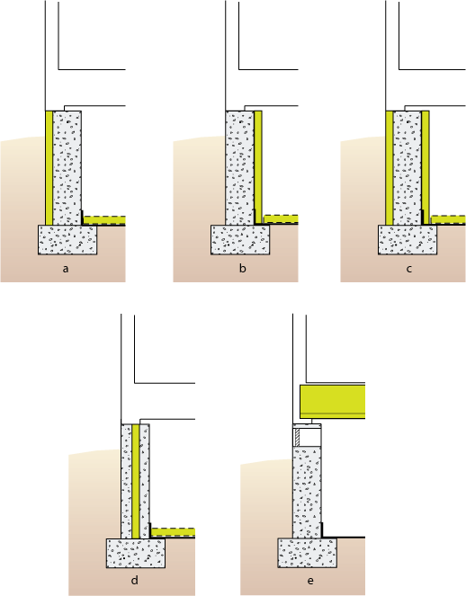
Effigy three-half dozen. Potential Locations for Crawl Space Insulation
LOCATION OF INSULATION
Another important factor to consider when managing moisture in a crawl space is the way it is to be insulated. Crawl spaces can be insulated at the exterior walls, or vented and insulated at the clamber space ceiling (Figure iii-six). Insulation not only plays a function in the thermal efficiency of a home but as well in the way that moisture behaves. Cooler surfaces in a crawl space can cause moisture from the air to condense on the surfaces. For unvented crawl spaces, the best approach is to treat the crawl space as a brusque basement, placing insulation on the exterior or interior surface of the crawl space walls. Inquiry has shown that closed crawl spaces with wall insulation have better free energy and moisture performance than wall-vented crawl spaces with ceiling insulation (Dastur et al. 2005).
A key question in the blueprint of an unvented crawl infinite is whether to place insulation inside or outside the wall. In terms of energy use, there is not a significant difference between the same corporeality of insulation applied to the exterior versus the interior of a concrete or masonry wall. However, the installation costs, ease of application, appearance, and diverse technical concerns tin exist quite unlike.
Rigid insulation placed on the exterior surface of a concrete (Figure 3-6a) or masonry wall has some advantages over interior placement in that it can provide continuous insulation with no thermal bridges, protect structural walls at moderate temperatures, and minimize moisture condensation problems (Figure 3-7). If the exterior insulation extends up over the rim joist and its R-value is high enough, the joists and sill plates tin exist left open to inspection from the interior for termites and decay. On the other hand, exterior insulation on the wall can be a path for termites and can prevent inspection of the wall from the exterior. If needed a termite barrier should be installed through the insulation where the sill plate rests on the foundation wall. This choice is shown in all drawings that draw outside crawl space foundation insulation. Vertical exterior insulation on a crawl space wall tin can extend as deep as the top of the ground and, if desired, be supplemented by extending the insulation horizontally from the confront of the foundation wall. Insulation that is exposed above grade must be protected with a coating to prevent physical damage and degradation. Such coatings include fiber cement board, parging (stucco type cloth), treated plywood, or membrane fabric (Baechler et al. 2005).
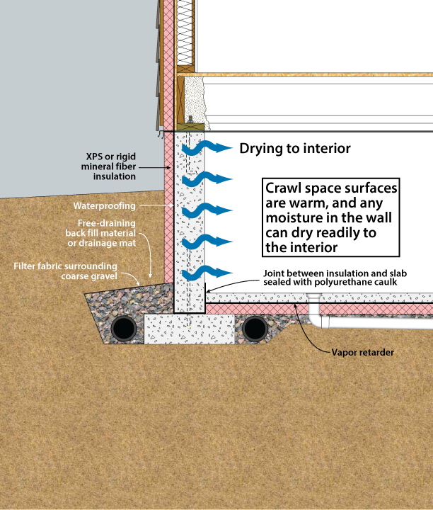
Figure 3-7. Crawl Infinite with Exterior Insulation
Exterior wall insulation must be approved for below-grade use. Typically, three products are used below grade: extruded polystyrene, expanded polystyrene, and rigid mineral fiber panels. (Baechler et al. 2005). Extruded polystyrene (nominal R-5 per inch) is a common selection. Expanded polystyrene (nominal R-four per inch) is less expensive, but it has a lower insulating value. Below-grade foams can exist at hazard for moisture accumulation under certain conditions. Experimental data indicate that this wet accumulation may reduce the constructive R-value as much as 35%-44%. Research conducted at Oak Ridge National Laboratories studied the moisture content and thermal resistance of foam insulation exposed beneath grade for 15 years; moisture may continue to accumulate and degrade thermal performance beyond the fifteen-yr time frame of the study. This potential reduction should be deemed for when selecting the amount and type of insulation to be used (Kehrer, et al., 2012, Crandell 2010).
Rigid fiberglass and rigid mineral wool panels (R-4 per inch) do not insulate as well as extruded polystyrene, merely are the only insulations that can provide a drainage space for foundation walls because of their porous construction. Use of these materials as a drainage space only works if effective ground perimeter drains are present.
Interior crawl space wall insulation (Figure 3-6b) is more common than exterior, primarily because it is less expensive since no protective covering is required, and can nowadays a reduced hazard of termite infestation. On the other manus, interior wall insulation may be considered less desirable than outside insulation considering information technology (ane) increases the exposure of the wall to thermal stress and freezing, (2) may increment the likelihood of condensation on sill plates, band joists, and joist ends, (iii) ofttimes results in some thermal bridges through framing members, and (iv) usually requires installation of a flame resistant cover. Interior insulation is non recommended on not-cadre filled masonry cake walls, due to an increased gamble of wet accumulation within the assembly. In addition, interior insulation should not be used if a positive capillary break is not present between the elevation of the foundation wall and wood framing arrangement due to the potential for wet accumulation in wood framing materials.
Materials that are resistant to moisture damage are recommended for use in contact with concrete foundation components. Rigid foam plastic or high-density spray polyurethane foam are the two materials recommended to insulate the interior side of walls in unvented crawl spaces (Figure three-8). In areas non decumbent to termite infestation, rigid foam should be installed and sealed at the rim joist to prevent entry of moist air into the wood structural components. This air bulwark is peculiarly critical in cold climates, and when exterior insulation is non installed. Batt insulation should only be used at the rim joist where access is required for termite inspections. Expanded or extruded polystyrene rigid cream insulation should be used to cover the walls and be attached with mechanical fasteners. A iii-inch wicking gap should be left between the wall insulation and the ground, and a three inch termite inspection gap or continuous termite shield should be present at the top of the wall and the sill plate (Marshall 2008). An ignition barrier or fire barrier will likely be required, based on code jurisdiction and occupancy.
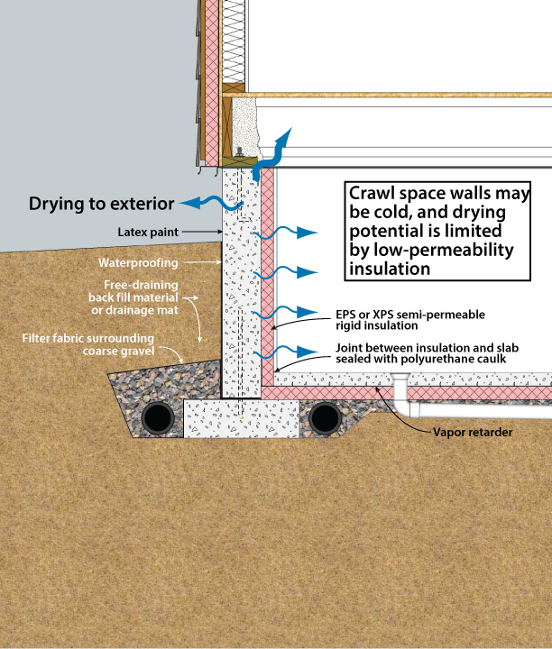
Figure 3-8. Crawl Space Interior Insulation with EPS or XPS Semi-Permeable Insulation on Inside Wall
Information technology is possible to eliminate the ignition barrier requirement. This has been done by using foil-faced polyisocyanurate insulation panels, which are rated for exposure in basements and clamber spaces in some jurisdictions. Annotation however that the unperforated foil facing is completely vapor-impermeable, and very trivial drying will occur through it. Many jurisdictions will as well allow high-density polyurethane cream to coat the rim and sill area (only not the entire wall) with no additional burn protection.
Interior insulation retrofits comport additional risks: capillary breaks may not be present, either at the top of the wall or between the foundation and the framing; insulating on the interior will tend to increase moisture aggregating in the framing in that case. A capillary break may not be present between the basis and the wall, potentially increasing the presence of moisture due to capillary wicking. Since waterproofing and drainage systems are often not present or not working on older houses, bulk water penetration is possible. For description of a robust retrofit interior insulation strategy see Ueno (2011).
Insulation placed horizontally around the crawl infinite floor perimeter can provide additional thermal protection for sealed crawl spaces with interior or exterior insulation on the foundation walls. However, it may as well create additional paths for termite entry. In common cold climates, insulation of the entire floor area to preclude rut loss may be desirable.
In a vented crawl space, the insulation is always located in the ceiling (Figures three-6e and three-9). There are two recommended approaches to clamber space ceiling insulation:
- Closed cell spray cream, applied to entirely encapsulate the structural members of the ceiling.
- Rigid foam (foil-faced polyisocyanurate is preferred) applied to the bottom face of the floor joists, all joints sealed and taped equally an air bulwark, with loose-make full or batt insulation to fill the cavity above (Figure three-9). Note that in common cold climates, the impermeable foil face volition serve as a vapor barrier on the incorrect (common cold) side of the assembly.
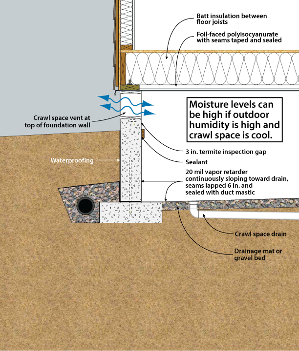
Figure 3-9. Vented Crawl Space with Insulation in the Ceiling
Effigy 3-x. Unvented Clamber Space with Interior Insulation - Designed for Termite Resistance (Heavily Infested Areas)
These systems are the just ones capable of preventing mold and disuse due to high humidity conditions that may occur in the crawl space in most climates (Lstiburek 2008). Impermeable floor finishes like vinyl flooring and some types of ceramic tile must be avoided to allow the floor to dry upward into the habitation.
In addition to more conventional interior or exterior placement covered in this handbook, in that location are several systems that incorporate insulation into the structure of the concrete or masonry walls. These include (1) rigid foam plastic insulation bandage within physical walls, (two) polystyrene beads or granular insulation materials poured into the cavities of conventional masonry walls, (three) systems of concrete blocks with insulating foam inserts, (4) formed, interlocking rigid foam units that serve as a permanent insulating form for cast-in-place concrete, and (5) masonry blocks made with polystyrene chaplet instead of aggregate in the physical mixture, resulting in significantly college R-values. However, the effectiveness of systems that insulate just a portion of the wall area should be evaluated closely considering thermal bridges around the insulation tin can touch on the full operation significantly.
TERMITE AND Forest Disuse Control TECHNIQUES
Techniques for decision-making the entry of termites through residential foundations are advisable in much of the U.s. (encounter Figures three-10 and 3-xi). Figure 3-10 shows an example for areas with a high likelihood of termite infestation; Effigy iii-11 shows an assembly for lower-risk parts of the country. The post-obit recommendations utilise where termites are a potential trouble. Consult with local building officials and codes for further details.
- Minimize soil moisture around the foundation by using gutters and downspouts to remove roof water, and by installing a consummate subdrainage organisation around the foundation.
- Remove all roots, stumps, and scrap wood from the site before, during, and after construction, including woods stakes and formwork from the foundation area.
- Treat soil with termiticide on all sites vulnerable to termites.
- Place a bond beam or course of solid cap blocks on top of all concrete masonry foundation walls to ensure that no open cores are left exposed. Alternatively, fill up all cores on the height course with mortar, and reinforce the mortar joint below the top grade.
- Identify the sill plate at least 8 inches above grade; it should be pressure-preservative treated to resist decay. The sill plate should exist visible for inspection from the interior. Since termite shields are frequently damaged or not installed advisedly enough, they should not be regarded equally sufficient defense by themselves.
- Be sure that exterior wood siding and trim is at least half-dozen inches above the concluding grade.
- Construct porches and outside slabs so that they slope abroad from the foundation wall and are at least 2 inches below exterior siding. In addition, porches and outside slabs should exist separated from all wood members by a 2-inch gap visible for inspection or by a continuous metal flashing soldered at all seams.
- Use pressure-preservative-treated wood posts within a crawl space, or place posts on flashing or on a concrete pedestal raised eight inches above the interior grade.
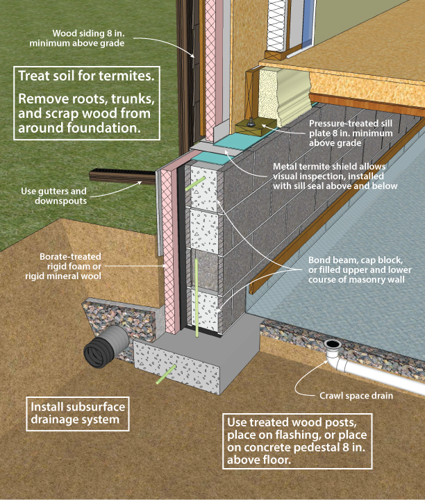
Figure iii-11. Unvented Physical Masonry Unit of measurement Clamber Space with Exterior Insulation - Designed for Termite Resistance (Moderately Infested Areas)
Plastic cream and batt insulation materials have no nutrient value to termites, but they can provide protective encompass and easy tunnelling. Insulation installations tin be detailed for ease of inspection, although often by sacrificing thermal efficiency.
In principle, termite shields offer protection, simply should not be relied upon as a barrier. Termite shields are shown in this document as a component of exterior insulation systems. Their purpose is to force whatever insects ascending through the wall out to the exterior, where they can be seen. For this reason, termite shields must be continuous, and all seams must be sealed to foreclose bypass by the insects.
These concerns over insulation and the unreliability of termite shields have led to the determination that soil handling is the most constructive technique to control termites with an insulated foundation. However, the restrictions on some traditionally used termiticides may make this option either unavailable or cause the commutation of products that are more expensive and peradventure less effective. This situation should encourage insulation techniques that enhance visual inspection and provide effective barriers to termites. For more information on termite mitigation techniques, see NAHB (2006).
RADON CONTROL TECHNIQUES
Structure techniques for minimizing radon infiltration into a clamber space are advisable if there is a reasonable probability that radon is present. To decide this, contact the state radon staff.
Effigy 3-12 shows an example for a vented crawl space; Figure iii-13 shows a vented case. General approaches to minimizing radon include (one) evacuating soil gas surrounding the basement, (two) sealing joints, cracks, and penetrations in the foundation, and (three) venting the clamber space while creating a continuous air barrier at the clamber space ceiling.
For ventilated crawl spaces
- For ventilated crawl spaces, provide substantial outside air ventilation. Place vents on all iv sides of the crawl space. A second more reliable radon control solution is to control and isolate the source as suggested for basement structure in Chapter two.
- Place a 6-mil polyethylene vapor retarder over all exposed soil floor areas. Overlap edges 12 inches and seal with mastic. Seal edges to the interior face of the foundation wall.
- Construct floors above unconditioned spaces with a continuous air infiltration barrier. Tongue and groove plywood floor decking should be applied with butt joints continuously glued to floor joists with a waterproof construction agglutinative. Seal all penetrations through the subfloor with caulk. Enclose big openings such as at bathroom tub drains with sheet metal or other rigid cloth and sealants.
- Avoid duct piece of work in the crawl infinite if possible, but it may be installed providing all joints are securely sealed with mastic, and ducts are well-insulated.
- Make crawl space walls separating an attached vented crawl space from a basement or living space as airtight equally possible.
For unvented clamber spaces
Sealing the Crawl Space Flooring
- Use solid pipes for floor discharge drains to daylight, or mechanical traps that belch to subsurface drains.
- Apply a half-dozen-mil (minimum) polyethylene moving picture beneath the slab (if one is present) on tiptop of the gravel drainage bed. This flick serves every bit a radon and moisture retarder and also prevents concrete from infiltrating the amass base under the slab as information technology is bandage. Slit an "x" in the polyethylene membrane to receive penetrations. Turn up the tabs and seal them to the penetration using caulk or tape. Care should exist taken to avoid unintentionally puncturing the barrier; consider using rounded riverbed gravel if possible. The riverbed gravel allows for freer move of the soil gas and also offers no sharp edges to penetrate the polyethylene. The edges of the film should be lapped at to the lowest degree 12 inches. The polyethylene should extend over the top of the basis, or be sealed to the foundation wall.
- Tool the joint between the wall and slab flooring (if nowadays) and seal with polyurethane caulk, which adheres well to concrete and is long-lasting.
- Avoid perimeter gutters around the slab that provide a straight opening to the soil beneath the slab.
- Minimize shrinkage cracking by keeping the water content of physical as low as possible. If necessary, use plasticizers, not h2o, to increase workability.
- Reinforce the slab (if present) with wire mesh or fibers to reduce shrinkage cracking, especially near the within corner of "L" shaped slabs.
- Where used, finish control joints with a one/2-inch depression and fully fill this recess with polyurethane or similar caulk.
- Minimize the number of pours to avoid cold joints. Begin curing the concrete immediately afterward the pour, co-ordinate to recommendations of the American Physical Institute (1980; 1983). At to the lowest degree three days are required at lxx °F, and longer at lower temperatures. Use an impervious cover sheet or wetted burlap to facilitate curing. The National Ready Mix Concrete Association suggests a pigmented curing compound should likewise be used.
- Form a gap of at least 1/ii-inch width around all plumbing and utility lead-ins through the slab to a depth of at least 1/2 inch. Fill with polyurethane or like caulking.
- Do not install sumps within crawl spaces in radon-prone areas unless absolutely necessary. Where used, comprehend the sump pit with a sealed chapeau and vent to the outdoors. Use submersible pumps.
- Install mechanical traps at all necessary floor drains discharging through the gravel beneath the slab.
- Place HVAC condensate drains so that they bleed to daylight outside the building envelope or to sealed sumps inside the basement. Condensate drains that connect to dry out wells or other soil may become direct paths for soil gas, and can be a major entry point for radon. At the very least make certain these condensate drains are properly trapped so that the full diameter of at least the department of an elbow is ever filled.
Sealing the Crawl Infinite Walls
- Reinforce walls and footings to minimize shrinkage bully and cracking due to uneven settlement.
- To retard movement of radon through hollow core masonry walls, the pinnacle and bottom courses of hollow masonry walls should be solid block, or filled solid. If the top side of the bottom grade is below the level of the slab, the course of block at the intersection of the lesser of the slab should be filled. Where a brick veneer or other masonry ledge is installed, the course immediately below that ledge should as well be solid cake.
- Parge and seal the outside face of below-form concrete masonry walls in contact with the soil. Install drainage boards to provide an airway for soil gas to accomplish the surface outside the wall rather than being drawn through the wall.
- Install a continuous dampproofing or waterproofing membrane on the exterior of the wall. Six-mil polyethylene-lapped, taped and placed on the outside of the crawl space wall surface volition retard radon entry through wall cracks.
- Seal around plumbing and other utility and service penetrations through the wall with polyurethane or like caulking. Both the outside and the interior of concrete masonry walls should exist sealed at penetrations.
- Install airtight seals on doors and other openings betwixt an unvented and adjoining vented crawl space.
- Seal effectually ducts, plumbing, and other service connections between an unvented and a vented crawl infinite.
- Exercise not identify air supply or return ducts under the slab or in the footing.
Intercepting Soil Gas
The most constructive manner to limit radon and other soil gas entry is through the utilise of active soil depressurization (ASD). ASD works by lowering the air pressure in the soil relative to the indoors. Avoiding foundation openings to the soil, or sealing those openings, every bit well every bit limiting sources of indoor depressurization aid ASD systems. Sometimes a passive soil depressurization (PSD, with no fan) system is used. If post-occupancy radon testing indicates further radon reduction is desirable, a fan can be installed in the vent pipe (run into Figure 3-13).
Subslab (or sub-membrane) depressurization has proven to exist an effective technique for reducing radon concentrations to adequate levels, even in homes with extremely high concentrations (Dudney 1988). This technique lowers the force per unit area around the foundation envelope, causing the soil gas to be routed into a collection arrangement, fugitive the inside spaces and discharging to the outdoors.
A foundation with good subsurface drainage already has a collection system. The subslab (or sub-membrane) gravel drainage layer can be used to collect soil gas. It should exist at least four inches thick, and of clean aggregate no less than ane/2 inch in diameter. The gravel should be covered with a half-dozen-mil polyethylene radon and wet retarder.
A 3- or 4-inch diameter PVC vent pipe should be routed from the gravel layer through the conditioned portion of the building and through the highest roof plane. The pipe should terminate below the slab or membrane with a "tee" plumbing fixtures. To prevent bottleneck the pipe with gravel, ten-foot lengths of perforated draintile tin can be fastened to the legs of the tee, and sealed at the ends. Alternately, the vent pipage can be connected to the perimeter bleed system, as long as that system does not connect to the outdoor surround. Horizontal vent pipes could connect the vent stack through below form walls to permeable areas below adjoining slabs or membranes. A unmarried vent piping is acceptable for well-nigh houses with less than two,500 square feet of floor area that also include a permeable subslab layer. The vent piping is routed to the roof through plumbing chases, interior walls, or closets.
A PSD system requires the floor to be about airtight and so that collection efforts are not short-circuited by cartoon excessive room air down through the air barrier and into the system. Cracks, penetrations, and control joints must be sealed. Sump hole covers should be designed and installed to be closed. Floor drains that discharge to the gravel beneath the slab should exist avoided, simply when used, should exist fitted with a mechanical trap capable of providing an airtight seal.
Another potential short circuit can occur if the subdrainage organisation has a gravity belch to an cloak-and-dagger outfall. This belch line may need to be provided with a mechanical seal. The subsurface drainage discharge line, if not run into a sealed sump, should be synthetic with a solid-glued drainpipe that runs to daylight. The standpipe should be located on the reverse side from this drainage discharge.
While a properly installed passive soil depressurization (PSD) system may reduce indoor radon concentrations by about l%, agile soil depressurization (ASD) systems can reduce indoor radon concentrations past up to 99%. A PSD system is more express in terms of vent pipe routing options, and is less forgiving of construction defects than ASD systems. Furthermore, in new structure, minor ASD fans (25-40 watt) may be used with minimal free energy impact. Active systems utilise placidity, in-line duct fans to describe gas from the soil. The fan should be located exterior, and ideally above, the conditioned space so that whatsoever air leaks from the positive pressure side of the fan or vent stack are not in the living space. The fan should be oriented to prevent accumulation of condensed water in the fan housing. The ASD stack should be routed up through the building or an attached garage or carport, and extend twelve inches above the roof. It can also be carried out through the band joist and up along the outside of wall, to a point high enough so that there is no danger of the exhaust being redirected into the edifice through attic vents or other pathways. Because PSD systems rely on natural buoyancy to operate, a PSD stack must be routed through the conditioned portion of the home.
A fan capable of maintaining 0.ii inch of h2o suction under installation conditions is adequate for serving subslab drove systems for most houses (Labs 1988). This is oft accomplished with a 0.03 hp (25W), 160 cfm centrifugal fan (maximum chapters) capable of drawing up to i inch of water earlier stalling. Under field conditions of 0.2 inch of water, such a fan operates at virtually 80 cfm.
PSD systems crave near perfection in sealing of openings to the soil, since the system relies on a 3- or 4-inch piping to vent more finer than the entire firm. Sealing openings to the soil is less critical for radon command with ASD systems, although it is highly desirable in order to limit the energy penalty associated with conditioned indoor air leaking into a depressurized subslab, and from in that location to the outdoors. ASD fans have service lives averaging nearly ten years, with a college life expectancy if the fan is protected from the elements. Since an ASD system may be turned off past occupants, service switches are unremarkably located in areas with limited access.
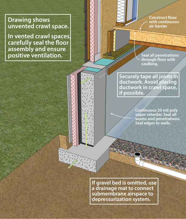
Figure 3-12. Crawl Space Radon Command Techniques
martinezprien1990.blogspot.com
Source: https://foundationhandbook.ornl.gov/handbook/section3-1.shtml
0 Response to "what type of fill is best to spread in a home crawl space?"
Postar um comentário